


TX12.5KSS PLUG-IN
COD. TX12.5KSS-60D41
Power: 12.500W
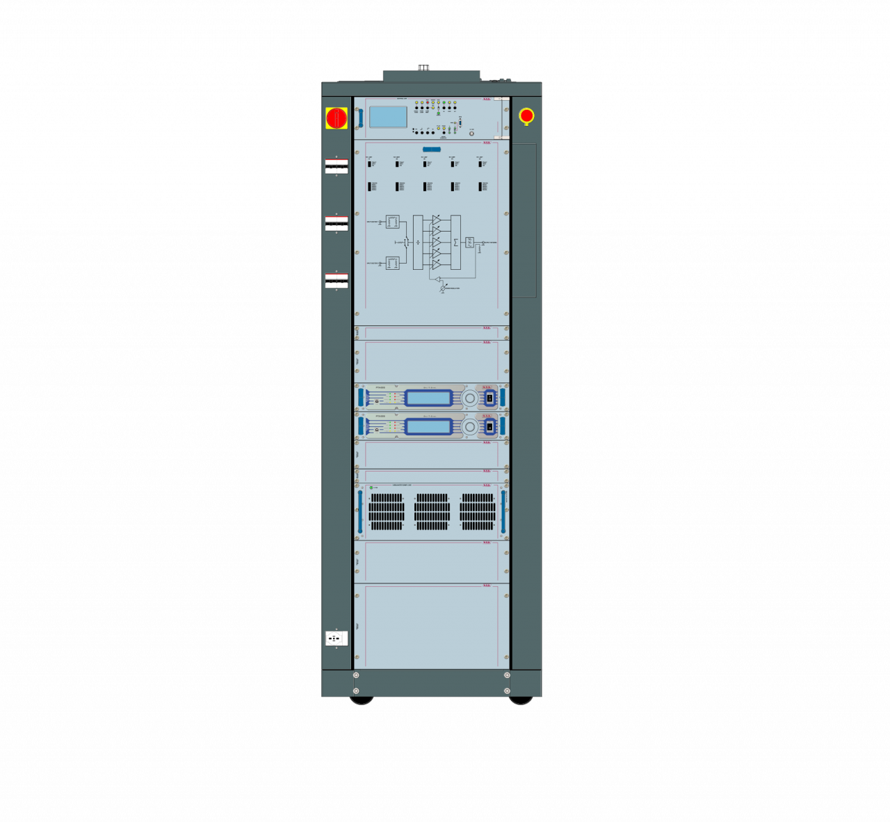
12.500W PLUG-IN System.
FEATURES
The image of this layout is purely demonstrative and may change without notice. The configuration is only referred to installed equipment; rack, cover panels and all others accessories are to be defined at order.
- Hot-pluggable and broadband power amplifier modules.
- Each module features switching mode power supply to control and stabilize power supply voltage.
- Each amplifier module provides Automatic Power Control.
- Suitable for mono & stereo broadcast operations.
- Protection against high VSWR, overdrive, overcurrent and overtemperature.
- Compliance to IEC safety standards.
- Compliance to ETSI – CCIR – FCC standards.
- Entire transmitter can be switched off through an emergency button.
- High redundancy guaranteed by 5 power modules of 2.5 kW RF power.
- All measurement and working parameters are displayed on front panel.
- Remotely controllable by telemetry system.
- Design for 24/7 non-stop operation.
- The transmitter include an integrated system for automatic and manual switching between two exciters.
- In Automatic mode the changeover is activated when active power of exciter falls below 3dB.
| TX12.5KSS/60D41 | |
| Parameter | Value |
| GENERALS | |
| RF Output Power | 12,5 kW |
| Frequency Range | 87,5 – 108 MHz |
| Frequency Stability | > 1 ppm |
| Frequency programmability | By software, with 1, 10, 100 , 1000 kHz steps |
| Nominal Frequency Deviation | ±75 KHz (peak) |
| Maximum Frequency Deviation | ±150 KHz (peak) |
| Class of Emission | 180KF8E Direct to Channel |
| Modulation Mode | Mono, Stereo, Multiplex, SCA, RDS, Aux |
| Stereo transmissions | Acc. to ITU-R / Rec. 450 (Pilot tone) |
| RF Output Impedance | 50 Ω, Unbalanced |
| RF Output Connector | 1-5/8” EIA Flange (3-1/8” EIA Flange on request) |
| VSWR | 1.4:1 with automatic fold-back at higher VSWR |
| Pre-emphasis Mode | 0/50 (CCIR) µs,75 (FCC) μs |
| Asynchronous AM S/N Ratio | Typically >70dB |
| Synchronous AM S/N Ratio | Typically > 55dB |
| Harmonics suppression and Spurious | Typically < 85dB |
| Overall efficiency | Typically > 70% |
| RF Harmonics | Exceeds ETSI/CCIR/FCC requirements |
| RF Spurious | Exceeds ETSI/CCIR/FCC requirements |
| Analogue Input level {+75 Khz (peak) deviation } | -12,5 dBu - +12,5 dBu (adjustable) |
| Digital Input level {+75 Khz (peak) deviation } | -20,0 dBFS – 0 dBFS (adjustable) |
| MONO OPERATION | |
| S/N ratio | Typically > 83dB |
| Total Harmonic Distortion + Noise | Typically < 0,03% |
| Inter Modulation Distortion SMPTE | Typically < 0,02% |
| Frequency Response | Typically ±0,2dB |
| Audio Input Impedance | 600 Ω or 10 kΩ |
| MPX OPERATION | |
| Composite S/N ratio | Typically > 80dB |
| Total Harmonic Distortion + Noise | Typically < 0,05% |
| Inter Modulation Distortion | Typically < 0,05% |
| Frequency Response | Typically ±0,2dB |
| Audio Input Impedance | 10 kΩ |
| STEREO OPERATION | |
| Stereo FM S/N Ratio | Typically > 83dB |
| Total Harmonic Distortion + Noise (L or R) | Typically < 0,02% |
| Inter Modulation Distortion SMPTE (L or R) | Typically < 0,02% |
| Frequency response (L or R) | Typically ±0,2dB |
| Linear Cross Talk | Typically > 50dB |
| Non-linear Cross Talk | Typically > 50dB |
| Stereo Separation (Sine Wave) | Typically > 70dB |
| Audio Input Impedance | 600 Ω or 10 kΩ |
| Digital Input Impedance | 110 Ω |
The image of this layout is purely demonstrative and may change without notice. The configuration is only referred to installed equipment; rack, cover panels and all others accessories are to be defined at order.
